Electronic symbol
An electronic symbol is a pictogram used to represent various electrical and electronic devices or functions, such as wires, batteries, resistors, and transistors, in a schematic diagram of an electrical or electronic circuit. These symbols are largely standardized internationally today, but may vary from country to country, or engineering discipline, based on traditional conventions.

Standards for symbols
The graphic symbols used for electrical components in circuit diagrams are covered by national and international standards, in particular:
- IEC 60617 (also known as BS 3939).
- There is also IEC 61131-3 – for ladder-logic symbols.
- JIC JIC (Joint Industrial Council) symbols as approved and adopted by the NMTBA (National Machine Tool Builders Association). They have been extracted from the Appendix of the NMTBA Specification EGPl-1967.
- ANSI Y32.2-1975 (also known as IEEE Std 315-1975[1] or CSA Z99-1975).
- IEEE Std 91/91a: graphic symbols for logic functions (used in digital electronics). It is referenced in ANSI Y32.2/IEEE Std 315.
- Australian Standard AS 1102 (based on a slightly modified version of IEC 60617; withdrawn without replacement with a recommendation to use IEC 60617).
The number of standards leads to confusion and errors.[2] Symbols usage is sometimes unique to engineering disciplines, and national or local variations to international standards exist. For example, lighting and power symbols used as part of architectural drawings may be different from symbols for devices used in electronics.
Common electronic symbols
Symbols shown are typical examples, not a complete list.[3][4]
Traces
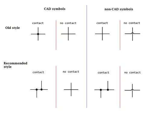
.svg.png.webp) Trace connection
Trace connection
(IEC-style).svg.png.webp) Trace junction
Trace junction
(IEC-style).svg.png.webp) Trace crossing (unconnected)
Trace crossing (unconnected) Trace crossing
(hand drawn schematics)
Grounds
The shorthand for ground is GND. Optionally, the triangle in the middle symbol may be filled in.
.svg.png.webp)
 Signal/low-noise ground (the asterisk is not part of the symbol)
Signal/low-noise ground (the asterisk is not part of the symbol).svg.png.webp) Chassis ground
Chassis ground
(IEC-style)
Sources
.svg.png.webp) Battery, single-cell
Battery, single-cell.svg.png.webp) Battery, multi-cell
Battery, multi-cell_8.7.3.svg.png.webp) Solar cell (photovoltaic cell)
Solar cell (photovoltaic cell)
 DC voltage source
 Controlled DC voltage source
 Current source
 Controlled current source
 AC voltage source
Resistors
It is very common for potentiometer and rheostat symbols to be used for many types of variable resistors, including trimmers.
%252C_and_Potentiometer_symbols.svg.png.webp)
 IEC-style: (a) Resistor, (b) Rheostat,
(c) Potentiometer / Trimmer
.svg.png.webp) Photoresistor (ANSI)
Photoresistor (ANSI).svg.png.webp)
_2.1.6.a.svg.png.webp) Varistor (ANSI)
Varistor (ANSI)
Capacitors
.svg.png.webp)
.svg.png.webp)
.svg.png.webp)
.svg.png.webp)

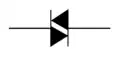
Diodes
Optionally, the triangle in these symbols may be filled in. Note: The words anode and cathode typically aren't part of the diode symbols.
 Diode (rectifier)


 Light-emitting diode (LED)


 Diac (may be a varistor in older schematics)
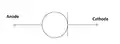
 Opto-isolator: LED (left), photo transistor (right)
Bridge rectifiers
There are many ways to draw a single-phase bridge rectifier symbol. Some show the internal diode circuit, some don't.
 Bridge rectifier
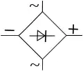 Bridge rectifier
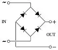 Bridge rectifier
.png.webp) Bridge rectifier
Bridge rectifier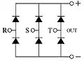 Three-phase bridge rectifier
Inductors

 Magnetic-core inductor
(IEEE-style) Tapped inductor
(IEC-style) Ferrite bead
(IEEE-style)
Transformers

 Transformer with center tap on secondary winding (right side)
 Transformer with two secondary windings (right side)
 Zero-sequence current transformer (ZSCT) (also known as a window-type current transformer)
 Bushing-type current transformer
 Voltage transformer
Transistors
Optionally, transistor symbols may include a circle.[6] Note: The pin letters B/C/E and G/D/S aren't part of the transistor symbols.
Bipolar
_8.6.2.svg.png.webp)
_8.6.1.svg.png.webp)
_8.6.17.svg.png.webp)

Unipolar
_8.6.10.1.b.svg.png.webp)
_8.6.11.1.b.svg.png.webp)


Vacuum tubes


Switches
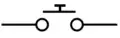 Pushbutton, normally open, push-to-make (horizontal line on top)
.svg.png.webp) Pushbutton, normally open, push-to-make (IEEE-style)
Pushbutton, normally open, push-to-make (IEEE-style).svg.png.webp) Pushbutton, normally closed, push-to-break (IEEE-style)
Pushbutton, normally closed, push-to-break (IEEE-style).svg.png.webp) Pushbutton, normally closed, two circuits (IEEE-style)
Pushbutton, normally closed, two circuits (IEEE-style)
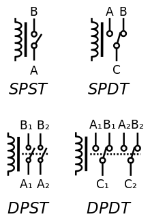
 Switch, 1P1T, SPST (single-pole single-throw)
 Switch, 1P2T, SPDT (single-pole double-throw)
 Switch, 2P1T, DPST (double-pole single-throw)
 Switch, 2P2T, DPDT (double-pole double-throw)
.svg.png.webp) Slide switch, 1P3T,
Slide switch, 1P3T,
break-before-make, nonshorting style.svg.png.webp) Slide switch, 1P4T,
Slide switch, 1P4T,
break-before-make, nonshorting style.svg.png.webp) Slide switch, 1P4T,
Slide switch, 1P4T,
make-before-break, shorting style
.svg.png.webp) Rotary switch, 1P3T,
Rotary switch, 1P3T,
break-before-make, nonshorting style.svg.png.webp) Rotary switch, 1P4T,
Rotary switch, 1P4T,
break-before-make, nonshorting style.svg.png.webp) Rotary switch, 1P4T,
Rotary switch, 1P4T,
make-before-break, shorting style
 Reed switch, normally open
Relays
Note: The pin letters aren't part of the symbols.
 SPST, SPDT, DPST, DPDT relays
(American-style) SPDT relay
(IEC-style)
Lamps
LED is located in diode section.

 Indicating lamp
(IEEE-style)
 Incandescent light bulb (as an indicator)
 Light bulb
Current limiters

 Molded-case circuit breaker (MCCB)
Electro-acoustic devices
 Loudspeaker
(IEEE-style) Buzzer
(IEC-style) Microphone
(IEEE-style) Microphone
(IEC-style)
Antennas
.svg.png.webp) General antenna
General antenna
(IEC-style).svg.png.webp) Dipole antenna
Dipole antenna
(IEC-style).svg.png.webp) Loop antenna
Loop antenna
(IEC-style).svg.png.webp) Loop antenna
Loop antenna
(IEEE-style)
Cables
.svg.png.webp) Cable, Shielded 1 conductor
Cable, Shielded 1 conductor.svg.png.webp) Cable, 2 conductor
Cable, 2 conductor.svg.png.webp) Cable, Shielded 2 conductor with shield connected to ground
Cable, Shielded 2 conductor with shield connected to ground.svg.png.webp) Cable, 5 conductor
Cable, 5 conductor.svg.png.webp) Cable, Shielded 5 conductor
Cable, Shielded 5 conductor
Connectors
 TRS phone jacks
ICs
Logic gates
For the symbols below: A and B are inputs, Q is output. Note: These letters are not part of the symbols.
There are variations of these logic gate symbols. Depending on the IC, the two-input gates below may have: 1) two or more inputs; 2) infrequently some have a second inverted Q output too.

 Inverter (NOT)


The above logic symbols may have additional I/O variations too: 1) schmitt trigger inputs, 2) tri-state outputs, 3) open-collector or open-drain outputs (not shown).
 Buffer gate with schmitt trigger input
 Buffer gate with tri-state output control.
(B is the tri-state control)
Flip-flops
For the symbols below: Q is output, Q is inverted output, E is enable input, internal triangle shape is clock input, S is Set, R is Reset (some datasheets use clear (CLR) instead of reset along the bottom).
There are variations of these flip-flop symbols. Depending on the IC, a flip-flop may have: 1) one or both outputs (Q only, Q only, both Q & Q); 2) one or both forced inputs along top & bottom (R only, S only, both R & S); 3) some inputs may be inverted.
 Simple SR flip-flop (inverted S & R inputs)
 Gated SR flip-flop
 Gated D flip-flop (Transparent Latch)
 Clocked D flip-flop
(Set & Reset inputs)_Symbol.svg.png.webp) Clocked JK flip-flop
Clocked JK flip-flop Clocked T flip-flop

Oscillators
.svg.png.webp) Crystal oscillator
Crystal oscillator
(IEEE-style) Ceramic resonator
(3 pins)
Miscellaneous devices
 Gas-discharge tubes (GDT) for ESD discharge
Historical electronic symbols
The shape of some electronic symbols have changed over time. The following historical electronic symbols can be found in old electronic books / magazines / schematics, and now considered obsolete.
Capacitors (historical)
All of the following are obsolete capacitor symbols.
 Obsolete capacitor
(very old style) Obsolete capacitor
 Obsolete capacitor
 Obsolete capacitor
 Obsolete capacitor
References
- "IEEE Standard American National Standard Canadian Standard Graphic Symbols for Electrical and Electronics Diagrams (Including Reference Designation Letters)," in IEEE Std 315-1975 (Reaffirmed 1993), vol., no., pp.i-244, 1993, doi:10.1109/IEEESTD.1993.93397.
- Guidelines for Drawing Schematics.
- Circuit Symbols for all Electronic Components. Talking Electronics, 2013. Retrieved 01 Apr 2015.
- Electrical Symbols & Electronic Symbols. RapidTables, 2012. Retrieved 17 April 2016.
- "Standards for Resistor Symbols". EePower. EETech Media. Retrieved September 13, 2021.
- "A4.11 Envelope or Enclosure". ANSI Y32.2-1975 (PDF).
The envelope or enclosure symbol may be omitted from a symbol referencing this paragraph, where confusion would not result
Further reading
- Beginner's Guide to Reading Schematics; 4th Ed; Stan Gibilisco; McGraw-Hill, 224 pages; 2018; ISBN 978-1260031119.
- How to Read Electronic Circuit Diagrams; 2nd Ed; Brown, Lawrence, Whitson; Tab Books; 214 pages; 1988; ISBN 978-0830628803.
- How to Read Schematic Diagrams; 4th Ed; Donald Herrington; Sams Publishing; 160 pages; 1986; ISBN 978-0672224577. (2nd Ed in 1967)
- Engineer's Mini-Notebook : Schematic Symbols, Device Packages, Design and Testing; 1st Ed; Forrest M. Mims III; Radio Shack; 48 pages; 1988.
External links
- IEEE Standard American National Standard Canadian Standard Graphic Symbols for Electrical and Electronics Diagrams (Including Reference Designation Letters)
- IEC 60617 : Graphical Symbols for Diagrams (2012) - International standard
- MIL-STD-806B : Graphical Symbols for Logic Diagrams (1962) - U.S. DoD standard