Package diagram
A package diagram in the Unified Modeling Language depicts the dependencies between the packages that make up a model.
| UML diagram types |
|---|
| Structural UML diagrams |
| Behavioral UML diagrams |
Overview
In addition to the standard UML Dependency relationship, there are two special types of dependencies defined between packages:
- package import
- package merge
A package import is "a relationship between an importing namespace and a package, indicating that the importing namespace adds the names of the members of the package to its own namespace."[1] By default, an unlabeled dependency between two packages is interpreted as a package import relationship. In this relationship, elements within the target package will be imported into the source package.
A package merge is "a directed relationship between two packages, that indicates that the contents of the two packages are to be combined. It is very similar to Generalisation in the sense that the source element conceptually adds the characteristics of the target element to its own characteristics resulting in an element that combines the characteristics of both"[2] In this relationship, if an element exists within both the source package and the target package, then the source element's definition will be expanded to include the target element's definition.
Elements
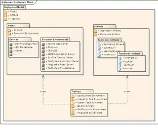
- Package: a general purpose mechanism for organising model elements & diagrams into groups. It provides an encapsulated namespace within which all the names must be unique. It is used to group semantically related elements. It is a namespace as well as an element that can be contained in other packages' namespaces.
- Class: a representation of an object that reflects its structure and behavior within the system. It is a template from which running instances are created. Classes usually describe the logical structure of the system.
- Interface: a specification of behavior. An implementation class must be written to support the behavior of an interface class.
- Object: an instance of a class. It is often used in analysis to represent an artifact or other item.
- Table: a stereotyped class.
Usage
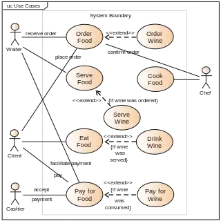
Package diagrams can use packages containing use cases to illustrate the functionality of a software system.
Package diagrams can use packages that represent the different layers of a software system to illustrate the layered architecture of a software system. The dependencies between these packages can be adorned with labels / stereotypes to indicate the communication mechanism between the layers.
When to use
- It is used in large scale systems to picture dependencies between major elements in the system
- Package diagrams represent a compile time grouping mechanism.
References
- [ OMG Unified Modeling Language (OMG UML), Infrastructure, V2.1.2] p. 149.
- OMG Unified Modeling Language (OMG UML), Infrastructure, V2.1.2 Archived 2017-01-09 at the Wayback Machine p. 160.


