Passband
A passband is the range of frequencies or wavelengths that can pass through a filter. For example, a radio receiver contains a bandpass filter to select the frequency of the desired radio signal out of all the radio waves picked up by its antenna. The passband of a receiver is the range of frequencies it can receive when it is tuned into the desired frequency (channel).
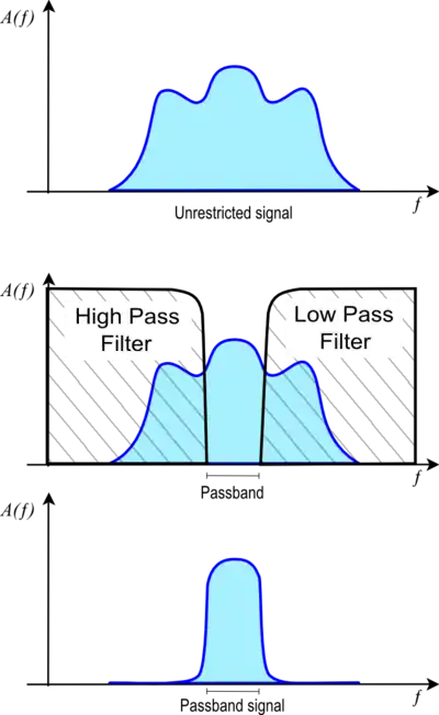
A bandpass-filtered signal (that is, a signal with energy only in a passband), is known as a bandpass signal, in contrast to a baseband signal.[1] The bandpass filter usually has two band-stop filters.
Filters

| Passband modulation |
|---|
 |
| Analog modulation |
| Digital modulation |
| Hierarchical modulation |
| Spread spectrum |
| See also |
|
In telecommunications, optics, and acoustics, a passband (a band-pass filtered signal) is the portion of the frequency spectrum that is transmitted (with minimum relative loss or maximum relative gain) by some filtering device. In other words, it is a band of frequencies which passes through some filter or a set of filters. The accompanying figure shows a schematic of a waveform being filtered by a bandpass filter consisting of a highpass and a lowpass filter.
Radio receivers generally include a tunable band-pass filter with a passband that is wide enough to accommodate the bandwidth of the radio signal transmitted by a single station.
Digital transmission
There are two main categories of digital communication transmission methods: baseband and passband.
- In baseband transmission, line coding is utilized, resulting in a pulse train or digital pulse amplitude modulated (PAM) signal. This is typically used over non-filtered wires such as fiber optical cables and short-range copper links, for example: V.29 (EIA/TIA-232), V.35, IEEE 802.3, SONET/SDH.
- In passband transmission, digital modulation methods are employed so that only a limited frequency range is used in some bandpass filtered channel. Passband transmission is typically utilized in wireless communication and in bandpass filtered channels such as POTS lines. It also allows for frequency-division multiplexing. The digital bitstream is converted first into an equivalent baseband signal, and then to a RF signal. On the receiver side a demodulator is used to detect the signal and reverse the modulation process. A combined equipment for modulation and demodulation is called a modem.
Details
In general, there is an inverse relationship between the width of a filter's passband and the time required for the filter to respond to new inputs. Broad passbands yield faster response times. This is a consequence of the mathematics of Fourier analysis.
The limiting frequencies of a passband are defined as those at which the relative intensity or power decreases to a specified fraction of the maximum intensity or power. This decrease in power is often specified to be the half-power points, i.e., 3 dB below the maximum power.
The difference between the limiting frequencies is called the bandwidth, and is expressed in hertz (in the optical regime, in nanometers or micrometers of differential wavelength).
The related term "bandpass" is an adjective that describes a type of filter or filtering process; it is frequently confused with "passband", which refers to the actual portion of affected spectrum. These two words are both compound words that follow the English rules of formation: the primary meaning is the latter part of the compound, while the modifier is the first part. Hence, one may correctly say 'A dual bandpass filter has two passbands'.
References
- Belle A. Shenoi (2006). Introduction to digital signal processing and filter design. John Wiley and Sons. p. 120. ISBN 978-0-471-46482-2.
 This article incorporates public domain material from Federal Standard 1037C. General Services Administration. Archived from the original on 2022-01-22. (in support of MIL-STD-188).