< Digital Circuits
AND gates is one the basic gates used to implement logical conjunction. It is basically a multiple input gate with a single output.
Electrical Analogy
It is analogous to a pair of switches in series which operates a bulb which is again in series with these switches. Thus, the bulb will be ON only when both the switches are closed. As seen from the truth table of an AND gate, the output will be HIGH only when all of its inputs are in logical 1 state.
Standard Symbols
 |
 |
 |
| MIL/ANSI Symbol | IEC Symbol | DIN Symbol |
Design using MOSFETs
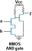
NMOS AND gate
The adjoining logic diagram shows the construction of an AND gate using N-Channel MOSFET. Alternatively, an AND gate can also be constructed using P-Channel MOSFET.
Truth Table
| A | B | Q | |
|---|---|---|---|
| 0 | 0 | 0 | |
| 0 | 1 | 0 | |
| 1 | 0 | 0 | |
| 1 | 1 | 1 |
| ||||||||||
This article is issued from Wikibooks. The text is licensed under Creative Commons - Attribution - Sharealike. Additional terms may apply for the media files.