Zonal safety analysis
Zonal Safety Analysis (ZSA) is one of three analytical methods which, taken together, form a Common Cause Analysis (CCA) in aircraft safety engineering under SAE ARP4761.[1] The other two methods are Particular Risks Analysis (PRA) and Common Mode Analysis (CMA). Aircraft system safety requires the independence of failure conditions for multiple systems. Independent failures, represented by an AND gate in a fault tree analysis, have a low probability of occurring in the same flight. Common causes result in the loss of independence, which dramatically increases probability of failure. CCA and ZSA are used to find and eliminate or mitigate common causes for multiple failures.
General Description
ZSA is a method of ensuring that the equipment installations within each zone of an aircraft meet adequate safety standards with respect to design and installation standards, interference between systems, and maintenance errors. In those areas of the aeroplane where multiple systems and components are installed in close proximity, it should be ensured that the zonal analysis would identify any failure or malfunction which by itself is considered sustainable but which could have more serious effects when adversely affecting other adjacent systems or components.
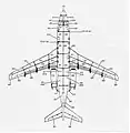
Aircraft manufacturers divide the airframe into zones to support airworthiness regulations, the design process, and to plan and facilitate maintenance. The commonly used aviation standard ATA iSpec 2200, which replaced ATA Spec 100, contains guidelines for determining airplane zones and their numbering. Some manufacturers use ASD S1000D for the same purpose. The zones and subzones generally relate to physical barriers in the aircraft. A typical zone map for a small transport aircraft is shown.[2]
 Zone Map of an Aircraft
Aircraft zones differ in usage, pressurization, temperature range, exposure to severe weather and lightning strikes, and the hazards contained such as ignition sources, flammable fluids, flammable vapors, or rotating machines. Accordingly, installation rules differ by zone. For example, installation requirements for wiring depends on whether it is installed in a fire zone, rotor burst zone, or cargo area.
ZSA includes verification that a system's equipment and interconnecting wires, cables, and hydraulic and pneumatic lines are installed in accordance with defined installation rules and segregation requirements. ZSA evaluates the potential for equipment interference. It also considers failure modes and maintenance errors that could have a cascading effect on systems,[3] such as:
- Flailing torque shaft
- Oxygen leak
- Accumulator burst
- Fluid leak
- Rotorburst
- Loose fastener
- Bleed air leak
- Overheated wire
- Connector keying error
Potential problems are identified and tracked for resolution. For example, if redundant channels of a data bus were routed through an area where rotorburst fragments could result in loss of all channels, at least one channel should be rerouted.
Case Studies
On July 19, 1989, United Airlines Flight 232, a McDonnell Douglas DC-10-10, experienced an uncontained failure of its No. 2 engine stage 1 fan rotor disk assembly. The engine fragments severed the No. 1 and No. 3 hydraulic system lines. Forces from the engine failure fractured the No. 2 hydraulic system line. With the loss of all three hydraulic-powered flight control systems, safe landing was impossible. The lack of independence of the three hydraulic systems, although physically isolated, left them vulnerable to a single failure event due to their close proximity to one another. This was a zonal hazard. The aircraft crashed after diversion to Sioux Gateway Airport in Sioux City, Iowa, with 111 fatalities, 47 serious injuries and 125 minor injuries.[4][5][6]
On August 12, 1985, Japan Air Lines Flight 123, a Boeing 747-SR100, experienced cabin decompression 12 minutes after takeoff from Haneda Airport in Tokyo, Japan, at 24,000 feet. The decompression was caused by failure of a previously repaired aft pressure bulkhead. Cabin air rushed into the unpressurized fuselage cavity, overpressurizing the area and causing failure of the auxiliary power unit (APU) firewall and the supporting structure for the vertical fin. The vertical fin separated from the airplane. Hydraulic components located in the aft body were also severed, leading to a rapid depletion of all four hydraulic systems. The loss of the vertical fin, coupled with the loss of all four hydraulic systems, left the airplane extremely difficult, if not impossible, to control in all three axes. Lack of independence of four hydraulic systems from a single failure event was a zonal hazard. The aircraft struck a mountain at forty-six minutes after takeoff with 520 fatalities and 4 survivors.[7]
See also
References
- Guidelines and methods for conducting the safety assessment process on civil airborne systems and equipment. Society of Automotive Engineers. 1996. ARP4761.
- Linzey, W. G. (2006). Development of an Electrical Wire Interconnect System Risk Assessment Tool (PDF). Federal Aviation Administration. DOT/FAA/AR-TN06/17. Retrieved 2011-02-19.
- Portwood, Brett (1998). System Safety Assessment. Federal Aviation Administration.
- Aircraft Accident Report-- United Airlines Flight 232, McDonnell Dougless DC-10-10, Sioux Gateway Airport, Sioux City, Iowa, July 19, 1989 (PDF). National Transportation Safety Board. 1990. NTSB/AAR-SO/06. Retrieved 2011-02-19.
- "Lessons Learned from Transport Airplane Accidents". Archived from the original on February 15, 2013. Retrieved February 24, 2015.
- "United Airlines Flight 232, DC-10". Federal Aviation Administration. 19 July 1989. Retrieved 2013-09-10.
- "Japan Airlines Flight 123, Boeing 747-SR100, JA8119". Federal Aviation Administration. 12 August 1985. Retrieved 2013-09-10.