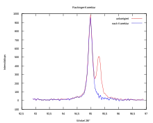
Rachinger correction
In X-ray diffraction, the Rachinger correction is a method for accounting for the effect of an undesired K-alpha 2 peak in the energy spectrum. Ideally, diffraction measurements are made with X-rays of a single wavelength. Practically, the x-rays for a measurement are usually generated in an X-ray tube from a metal's K-alpha line. This generation creates x-rays at a variety of wavelengths, but most of the non K-alpha X-rays can be blocked from reaching the sample by filters. However, the K-alpha line is actually two x-ray lines close together: the stronger K-alpha 1 peak, and the weaker K-alpha 2 peak. Compared to other radiation such as the Bremsstrahlung, the K-alpha two peak is more difficult to filter mechanically. The Rachinger correction is a recursive method suggested by William Albert Rachinger (1927) to eliminate the disturbing peak.[1]
Cause of the double peak
For diffraction experiments with X-rays radiation is usually used with the Wavelength of the anode material . However, this is a doublet, so in reality two slightly different wavelengths. According to the diffraction conditions of the Laue or Bragg equation, both wavelengths each generate an intensity maximum. These maxima are very close to each other, with their distance depending on the diffraction angle . For larger angles, the distance of the intensity maxima is greater.
Procedure
Basics
The wavelengths of and radiation are also known to increase their energy through the relationship:
From this, the angular distance can be determined for each diffraction angle determine the two Kα peaks.
Furthermore, it is known how the intensities of and behave in the diffraction pattern. This ratio is determined quantum mechanically and is for all anode materials:
Calculation
The total intensity is:
,
where is the intensity of the pure peak and the intensity of the pure peak.
The intensity of peak can be expressed as:
,
so the overall intensity is:
Practical Implementation

To practically perform the Rachinger correction, one starts on a rising edge of a peak. For a certain angle becomes the intensity of the diffraction image take and with scales with , at the same time the angle difference becomes te calculated . At the point can the true intensity (which, if there is no peak) would be calculated by: .
Since the measured values of X-ray diffraction experiments are usually available as ASCII tables, this procedure can be repeated step by step until the entire diffraction pattern has been run through.
Today this method is hardly used anymore. Due to the power of the computers, the peak can be fit simultaneously.
Restrictions
From the way the corrected diffraction image is calculated, it follows that no correction is made for the small diffraction angles. Furthermore, the assumption Rachinger that it is Peak just a scaled variant of the peaks are not correct, as the lines generally have different widths.[2] Therefore, in reality there is a deviation in form and intensity. Also, the correction loses its validity for a non-negligible background, since this itself causes an unwanted correction.
Literature
- Rachinger, William Albert (1948). "A Correction for the α1 α2 Doublet in the Measurement of Widths of X-ray Diffraction Lines". Journal of Scientific Instruments. IOP Publishing. 25 (7): 254–255. doi:10.1088/0950-7671/25/7/125. ISSN 0950-7671.
- Warren, B. E. (1969). X-ray Diffraction. Dover Publications. ISBN 0-486-66317-5.
References
- Brent Fultz; James Howe (29 June 2013). Transmission Electron Microscopy and Diffractometry of Materials. Springer Science & Business Media. p. 706. ISBN 978-3-662-04901-3. Retrieved 5 April 2019.
- Krause, M. O.; Oliver, J. H. (1979). "Natural widths of atomic K and L levels, Kα X‐ray lines and several KLL Auger lines". Journal of Physical and Chemical Reference Data. AIP Publishing. 8 (2): 329–338. Bibcode:1979JPCRD...8..329K. doi:10.1063/1.555595. ISSN 0047-2689.