Director (military)
A director, also called an auxiliary predictor,[1] is a mechanical or electronic computer that continuously calculates trigonometric firing solutions for use against a moving target, and transmits targeting data to direct the weapon firing crew.
Naval warships
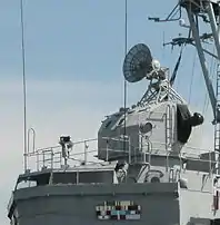
For warships of the 20th century, the director is part of the fire control system; it passes information to the computer that calculates range and elevation for the guns. Typically, positions on the ship measured range and bearing of the target; these instantaneous measurements are used to calculate rate of change values, and the computer ("fire control table" in Royal Navy terms) then predicts the correct firing solution, taking into account other parameters, such as wind direction, air temperature, and ballistic factors for the guns. The British Royal Navy widely deployed the Pollen and Dreyer Fire Control Tables during the First World War, while in World War II a widely used computer in the US Navy was the electro-mechanical Mark I Fire Control Computer.
On ships the director control towers for the main battery are placed high on the superstructure, where they have the best view. Due to their large size and weight, in the World War II era the computers were located in plotting rooms deep in the ship, below the armored deck on armored ships.
Field artillery
Directors were introduced into field artillery in the early 20th century to orient the guns of an artillery battery in their zero line (or 'centre of arc'). Directors were an essential element in the introduction of indirect artillery fire. In US service these directors were called 'aiming circles'. Directors could also be used instead of theodolites for artillery survey over shorter distances. The first directors used an open sight rotating on an angular scale (e.g. degrees & minutes, grads or mils of one sort or another), but by World War I most directors were optical instruments. Introduction of digital artillery sights in the 1990s removed the need for directors.
Directors were mounted on a field tripod and oriented in relation to grid north of the map. If time was short this orientation usually used an integral compass, but was updated by calculation (azimuth by hour angle or azimuth by Polaris) or 'carried' by survey techniques from a survey control point. In the 1960s gyroscopic orientation was introduced.
Anti-aircraft
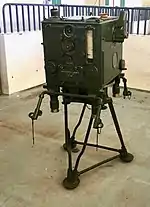
For anti-aircraft use, directors are usually used in conjunction with other fire control equipment, such as height finders or fire control radars.[2] In some armies these 'directors' were called 'predictors'. The Mark 51 director was used by the US Navy for 40 mm guns and later for 3"/50 caliber guns.[3] The Kerrison Predictor was also designed to be used with the Bofors 40 mm gun.
Example
The Bofors 40 mm gun (called a fire unit) used in its anti-aircraft role has the M5 director for its fire-control system.[4] The director is operated by a member of the range section who reports to the chief of section, who in turn reports to the platoon commander. The range section's leader is also called a range setter; he guides the preparation of the director and generator for firing, verifies the orientation and synchronisation of the gun and the director, and supervises fire control using the M5 director (or by the carriage when the M7 Weissight is used). The range section that uses the M5 director consists of the range setter, elevation tracker, azimuth tracker, power plant operator and telephone operator.
The M5 director is used to determine or estimate the altitude or slant range of the aerial target. Two observers then track the aircraft through a pair of telescopes on opposite sides of the director. The trackers turn handwheels to keep the crosshairs of their respective telescope on the aircraft image. The rotation of the handwheels provides the director with data on the aircraft's change in elevation and change in azimuth in relation to the director. As the mechanisms inside the director respond to the rotation of the handwheels, a firing solution is mechanically calculated and continuously updated for as long as the target is tracked. Essentially, the director predicts future position based on the aircraft's present location and how it is moving.
After their introduction, directors soon incorporated correction factors that could compensate for ballistic conditions such as air density, wind velocity and wind direction. If the director was not located near the gun sections, a correction for parallax error could also be entered to produce even more accurate firing direction calculations.[5]
Directors transmit three important calculated firing solutions to the anti-aircraft gun firing crew: the correct firing azimuth and quadrant elevation calculated to determine where exactly to aim the gun, and for guns that use ammunition with timed fuzes, the director also provides the flight time for the projectile so the fuze can be set to detonate close to the target.
Early anti-aircraft artillery batteries located the directors in the middle of the position, with the firing sections (guns) located at the corners of the position.[6] Before the introduction of radars, searchlights were used in conjunction with directors to allow night target engagement.[7]
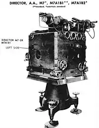
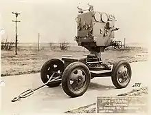
U.S. Army anti-aircraft directors

- T1 (wilson) director
- T4 gun director used with 3-inch M1918 gun
- T6 was built by Sperry Corporation in 1930 and standardized as the M2 director.
- M3 was standardized from the T8 in 1934
- M4 was standardized in 1939
- M5 Gun Director Mechanical, a US-produced Kerrison Predictor, for use with 37mm Gun M1 and M1 40 MM
- M5A1
- M5A2
- M7 gun director was standardized in 1941, and is similar to the M4 but added power control to the guns it is still described as a mechanical system. for use with 90 mm gun
- M7A1B1
- M7A1B2
- T10 standardized as M9 Gun Director electrical[8] for use with 90 mm gun produced by Bell Labs
- M9B1
- M10 gun director electrical for use with 120 mm M1 gun
Naval directors
- Mark 1
- MK 51 Fire Control System
- Mark 56
- Mark 57
- Mark 58
- Mark 59
- Mark 92
- Type 6 director (PRC)
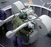 A late Cold War era U.S. Navy Mark 115 Sea Sparrow fire control system director on board a Nimitz-class aircraft carrier.
 A modern Royal Navy director on board a Type 42 destroyer.
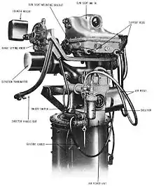 A U.S. Navy Mark 51 director for Bofors 40 mm guns, circa 1958.
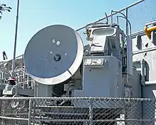 A Cold War era U.S. Navy MK-56 director on board USS Hornet.
Surviving examples
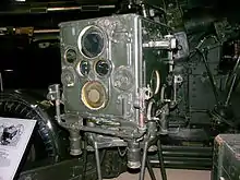
- South African National Museum of Military History - Number 1 Mark II Predictor
- Powerhouse Museum - Vickers No.1 anti-aircraft predictor, 1942[9]
- USS Texas, museum ship, Houston, Texas. Mark 51 anti-aircraft directors.
See also
- Ship gun fire-control systems
- Rangekeeper
- Gun data computer
- Fire-control system
- Indirect fire
- Hendrik Wade Bode, designer of US T10 director.
- John Whitney (animator), Used M5 AA director for film animation.
Notes
- , Lone Sentry
- "Skylighters: An Introduction to Antiaircraft Artillery and Searchlights". skylighters.org.
- Mark 51 Article on the Mark 51 director at NavWeaps.com
- , Brooks Directors and height finders
- p.23, Brown
- p.172, Journal of the United States Artillery
- p.352, Dow Boutwell, Brodinsky, Frederick, Pratt Harris, Nixon, Takudzwa Chaita, Robertson
- also known as the BTL 10 predictor, p.170, Bennett
- "Vickers No.1 anti-aircraft predictor, 1942". Powerhouse Museum.
References
- TM 9-2300 Standard Artillery and Fire Control Materiel dated 1944
- Brooks, Brian L., Antiaircraft command: Preserving the history of U.S.Army antiaircraft artillery of World War II, Directors and height finders,
- Lone Sentry.com, German Antiaircraft Artillery, Military Intelligence Service, Special Series 10, Feb. 1943, U.S. War Department, 1943
- Skylighters, A Beginner's Guide to the Skylighters, WW II Antiaircraft Artillery, Searchlights, and Radar, Skylighters.org Archived 2016-04-05 at the Wayback Machine January 10, 2004
- Brown, Louis, A Radar History of World War II: Technical and Military Imperatives, CRC Press, 1999
- Journal of the United States Artillery, v. 47, Artillery School (Fort Monroe, Va.), Coast Artillery Training Center (U.S.), 1917
- Dow Boutwell, William, Brodinsky, Ben, Frederick, Pauline, Pratt Harris, Joseph, Nixon, Glenn, Robertson, Archibald Thomas, America Prepares for Tomorrow; the Story of Our Total Defense Effort, Harper and brothers, 1941
- Evans, Nigel F., Laying and Orienting the Guns
- Bennett, Stuart, A History of Control Engineering, 1930–1955, IET, 199
- The Coast Artillery Journal, May/June 1935
Further reading
- Mindell, David (December 1995). "Automation's Finest Hour: Bell Labs and Automatic Control in World War II" (PDF). IEEE Control Systems Magazine. 15 (6): 72–78 80. doi:10.1109/MCS.1995.476388. S2CID 10041704.
External links
- Mark 51 Gun director
- Director Firing Handbook index from HMS Dreadnought project
- Gunnery Pocket book maritime.org
- http://web.mit.edu/STS.035/www/PDFs/sperry.pdf
- https://books.google.com/books?id=sExvSbe9MSsC&q=Between+Human+and+Machine
- https://books.google.com/books?id=T-IDAAAAMBAJ&dq=m16+gun+data+computer&pg=PA801
- Gun Fire Control System Mark 37 Operating Instructions at ibiblio.org
- Director section of Mark 1 Mod 1 computer operations at NavSource.org