Immittance
Immittance is a term used within electrical engineering and acoustics, specifically bioacoustics and the inner ear, to describe the combined measure of electrical or acoustic admittance and electrical or acoustic impedance. Immittance was initially coined by H. W. Bode in 1945, and was first used to describe the electrical admittance or impedance of either a nodal or a mesh network. Bode also suggested the name "adpedence", however the current name was more widely adopted. In bioacoustics, immittance is typically used to help define the characteristics of noise reverberation within the middle ear and assist with differential diagnosis of middle-ear disease.[1] Immittance is typically a complex number which can represent either or both the impedance and the admittance (ratio of voltage to current or vice versa in electrical circuits, or volume velocity to sound pressure or vice versa in acoustical systems) of a system.[3] Immittance does not have an associated unit because it applies to both impedance, which is measured in ohms (Ω) or acoustic ohms, and admittance, which is commonly measured in siemens (S) and historically has also been measured in mhos (℧), the reciprocal of ohms.
| Immittance | |
|---|---|
 Combined measure of impedance, admittance, or both. Immittance is crucial to several practices, such as tympanometry. | |
Common symbols | W, Za, Ya,[1] C, F, t, ∈, ℝ, jt, ϵ, χ, M[2] |
| SI unit | N/A |
Notable usage
Bioacoustics
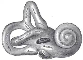
In audiology, tympanometry is sometimes referred to as immittance testing. Tympanometry is especially effective when both the impedance and admittance of the inner ear are accounted for. Immittance allows for the analysis of both, and therefore is crucial to multiple-component, multiple-frequency tympanometry. Clinically, few cases require the use of this technique for accurate diagnosis; but for the fewer than 20% of cases which do require it, the technique is a necessity. Multiple-component, multiple-frequency tympanometry is invaluable for the differential diagnosis of fixation of the lateral ossicular chain from fixation of the stapes, profound mixed hearing losses, clinical otosclerosis from disruption of the ossicular chain, hypermobility of the incudostapedial joint, and congenital ossicular fixation in children.[4]
Electrical engineering
In electronics, an immittance Smith chart can be created by overlaying both the impedance and admittance grids, which is useful for cascading series-connected with parallel-connected electric circuits. This allows for the visualization of changes in impedance or admittance in the system caused by components of either the series or parallel circuit. [5]
References
- Lilly, David (2005-04-20). "The Evolution of Aural Acoustic-Immittance Measurements". The ASHA Leader. 10 (5): 6–24. doi:10.1044/leader.FTR2.10052005.6. ISSN 1085-9586.
- Malkow, Dr. Ing T (27 September 2017). "Immittance Data Validation by Kramers‐Kronig Relations – Derivation and Implications". ChemElectroChem. 4 (11): 2777–2782. doi:10.1002/celc.201700630. PMC 5861665. PMID 29577007.
- Scanlan, J. O. (2020). "Immittance". McGraw Hill's AccessScience. Retrieved 2023-05-20.
- Sacramento, Sacramento ENT 1111 Exposition Blvd; Office:736-3399, CA 95815. "Immittance Testing". Sacramento ENT. Retrieved 2023-05-20.
- "The Immittance Smith Chart - Impedance Matching with only L and C". www.antenna-theory.com. Retrieved 2023-05-20.