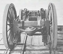
Cannon bearing
A cannon bearing or cannon box bearing is an arrangement of bearings on a shaft, usually an axle, where two bearings are mounted in an enclosed tube.
The function of the cannon box is to preserve the alignment of the two bearings, even if the overall tube is allowed to move. The two bearings will retain their same relative position. The bearing tube can be attached to the vehicle frame through either a pivot or springs.
The name 'cannon box' derives from the appearance of the hollow tube. Also from the boring machines used to machine the accurately aligned bearing seats, the same machines developed for the boring of cannon and also used for machining the cylinders of steam engines.
Cannon box bearings are still found today, although much of the need for them was removed by the development of self-aligning ball bearings. These allow the inner race of a bearing to move independently of its outer, so that each bearing can align to both shaft and housing simultaneously, even if the housing moves around.
Railway use

The 'cannon box' bearing was introduced by George Stephenson on his locomotive Locomotion of 1825 for the Stockton and Darlington Railway.[1] One of the axles was carried in a 'cannon box' bearing that was pivoted centrally and could tilt from side to side.[1] Unlike Stephenson's earlier locomotives and their steam springs, this new suspension had no springing but was a compensated suspension: as one side was raised, the bearing tube pivoted and the other side was pushed downwards. Although not giving a stable ride for the locomotive, it did allow the wheels to follow uneven track. Rails of this period were short pieces of cast iron rather than lengths of rolled steel and had frequent, often misaligned, joints.
A side-effect of the cannon box is that the centre of the shaft is now enclosed and inaccessible. Previously Stephenson had coupled the driving axles of his locomotives with a central chain. The need for an alternate system spurred the development of the coupling rods,[1] where the drive was connected on the outside face of the wheels.
The enclosure of the shaft and bearing also had advantages for enclosing the bearings to exclude dirt and to contain lubricating oil.[2]
Francis Webb's form of radial axle design for the LNWR used a cannon box. A radial axle is a form of single axle pony truck, where instead of a pivoted frame, the two axle bearings can slide sideways in a circular track. Webb's design placed them into a curved cannon box. David Joy, designer of the eponymous valvegear, described encountering these axleboxes on Webb's Precedent class.[3] The earlier Adams design for a similar axle had relied on the axle and thrust-faces within the axle bearings to keep the hornblocks in position.
In the 1920s, some electric locomotives used rigid frames with a leading and trailing truck, where a cannon bearing was a convenient inside-framed bearing for the truck. The Swiss 'Java bogie' design, developed by Jakob Buchli, even used this for a driving axle, with the drive provided by a one-sided Buchli drive outside the wheels.
Roller bearings, and their enclosing cannon boxes, were used for the British Railways Standard classes, on bogie axles and also on the driving axles of some of the larger classes.[4] This use was simplified, as the Standard classes (with the unique exception of the single Class 8) had just two outside cylinders. Railway use of such bearings continues today. The Peppercorn Class A1 Tornado replica uses roller bearings rather than the original plain bearings and these use cannon tube bearings for both the driving and bogie axles, although not for the central cylinder's crank axle.[5]
The rigidity of the cannon box also allows the faces of the axleboxes which move up and down in the hornguides to only need a single horn flange. Conventional axleboxes have a pair of flanges with the guide between them, so that they can move up and down for suspension without any axial movement. If they are both held at the correct spacing by the cannon tube, only one flange is needed.[2] The thinner axlebox, without the external flange, can allow the hornguides and frames to be placed closer to the inner face of the wheel, giving better support for a heavily-loaded axle.
Traction engines
Traction engines began as agricultural vehicles and ignored springing or suspension on their main wheels. As light steam tractors developed from 1896 for road haulage though,[6] locomotives with solid rubber tyres and suspension became favoured. The driving wheels of a traction engine are carried on a single axle, running closely behind the rear plate of the boiler firebox and carried in bearings fitted to the hornplates on either side of the boiler. Where springs were used, the cannon box bearing was favoured for maintaining the bearing alignment, with a further advantage of enclosing the axle away from the coal and ash from the firebox. Designs such as the Tasker Little Giant[7][8] used another compensated suspension, where the tube was suspended from a single transverse leaf spring.
References
- Bailey, Michael R. (2014). "The George Stephenson Types, 1820s". Loco Motion. The History Press. pp. 35–36. ISBN 978-0-7524-9101-1.
- Ransome-Wallis, P., ed. (2001) [1959]. Encyclopedia of World Railway Locomotives. Dover Transportation. Courier Corporation. pp. 243, 245. ISBN 0486412474.
- Joy, David (September 1884). Diaries.
- Allen, G. Freeman (1959). British Railways today and tomorrow. Ian Allan. p. 37.
- "Significant Progress". Tornado Trust. 29 April 2009.
- Whitehead, Robert A. (1970). "1: Origins and Makers". The Age of the Traction Engine. Ian Allan. p. 25. ISBN 0-7110-0129-4.
- Whitehead (1970), p. 27.
- "'Little Giant' Tractor". Army Service Corps Training, Mechanical Transport. 1911. pp. 194–195.