< Practical Electronics
Parallel RC
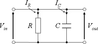
Circuit Impedance


Circuit Response


Parallel RL
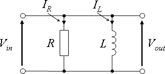
Circuit Impedance


Circuit Response


Parallel LC

Circuit Impedance


Circuit response


Parallel RLC
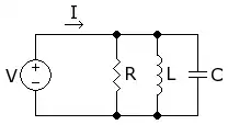
Circuit Impedance


Circuit response


Natural Respond

Forced Respond

Second ordered equation that has two roots
- ω = -α ±

Where


The current of the network is given by
- A eω1 t + B eω2 t
From above
- When , there is only one real root
- ω = -α

- When , there are two real roots
- ω = -α ±

- When , there are two complex roots
- ω = -α ± j


Resonance Response
At resonance, the impedance of the frequency dependent components cancel out . Therefore the net voltage of the circui is zero
and


At Resonance Frequency
- .
- . Current is at its maximum value
Further analyse the circuit
- At ω = 0, Capacitor Opened circuit . Therefore, I = 0 .
- At ω = 00, Inductor Opened circuit . Therefore, I = 0 .
With the values of Current at three ω = 0 , , 00 we have the plot of I versus ω . From the plot
If current is reduced to halved of the value of peak current , this current value is stable over a Frequency Band ω1 - ω2 where ω1 = ωo - Δω, ω2 = ωo + Δω


- In RLC series, it is possible to have a band of frequencies where current is stable, ie. current does not change with frequency . For a wide band of frequencies respond, current must be reduced from it's peak value . The more current is reduced, the wider the bandwidth . Therefore, this network can be used as Tuned Selected Band Pass Filter . If tune either L or C to the resonance frequency . Current is at its maximum value . Then, adjust the value of R to have a value less than the peak current by increasing R to have a desired frequency band .
- If R is increased from R to 2R then the current now is which is stable over a band of frequency
- ω1 - ω2 where
- ω1 = ωo - Δω
- ω2 = ωo + Δω
For value of I < . The circuit respond to Wide Band of frequencies . For value of < I > . The circuit respond to Narrow Band of frequencies
Summary
| Circuit | Symbol | Series | Parallel |
|---|---|---|---|
| RC | 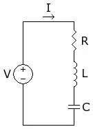 | A parallel RC Circuit | |
| Impedance | Z | ||
| Frequency | | | |
| Voltage | V | ||
| Current | I | ||
| Phase Angle | Tan θ = 1/2πf RC f = 1/2π Tan CR t = 2π Tan CR | Tan θ = 1/2πf RC f = 1/2π Tan CR t = 2π Tan CR |


This article is issued from Wikibooks. The text is licensed under Creative Commons - Attribution - Sharealike. Additional terms may apply for the media files.