A few words about OpenSCAD
OpenSCAD is a solid 3D modeler that enables the creation of parametric models using its scripting language. Models are created by utilizing a technique called constructive solid geometry. According to this technique, simple objects can be transformed and combined in order to create almost any complex model.
Getting started with the Tutorial
This tutorial is a follow along tutorial. As you are following the examples you will be asked to modify and extend them as well as create your own models. To move on please install OpenSCAD and start from a blank model.
Basic information about the OpenSCAD environment
The first thing that you should notice is that the window of OpenSCAD is divided into two columns. The left column is a text editor, where you will be typing the OpenSCAD scripting language to create your models. Any model that you are ever going to create is going to be "typed out" in this text editor. The top of the right column is the "virtual" 3D space where your models will exist. The only thing that you should currently be able to find there is the annotated reference axes X, Y and Z. The bottom of the right column is the console, where OpenSCAD will be printing any error messages or other information as you build your models. One final thing that you should notice is the presence of one action bar over the text editor and one below the reference axes. You will be introduced to the available actions and you will use them as the tutorial moves on.

Creating your first object
Your first object is going to be a perfect cube with side length of 10. In order to create it you need to type the following code in the text editor and hit the preview (first) icon on the action bar below the reference axes.
|
a_small_cube.scad cube(size=10); |
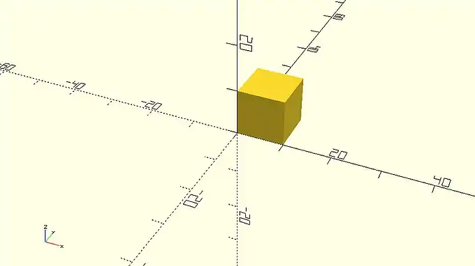
There are a few fundamental concepts that you should set straight from the start regarding the OpenSCAD scripting language, especially if you don’t have a programming background. The word cube is part of OpenSCAD scripting language and is used to command OpenSCAD to create a cube. The cube command is followed by a pair of parentheses, inside of which the parameter size is defined to be 10. Any definition of parameters that a command may require is always done inside a pair of matching parentheses that follow the command word. The semicolon after the last parenthesis indicates the end of this statement and helps OpenSCAD to parse the script that you have typed in the text editor. Because a semicolon is used to indicate the end of each statement you have the freedom to format your code in any way you like by inserting whitespace.
| Try adding some whitespace between the word cube and the first parenthesis and then hit preview. Is your cube created? Do you get any error message? Try adding some additional whitespace in different places and hit preview again to see what you can get away with before getting an error message in the console. What happens if you add whitespace between the syllables cu and be of the word cube and hit preview? What happens if you delete the semicolon? |
You just read "hit preview" three times in the last paragraph. When you hit preview OpenSCAD parses your script and creates the appropriate model. Every time you make a change to your script (ex. adding whitespace) or later when adding additional statements, you need to hit preview to see the effect of these changes.
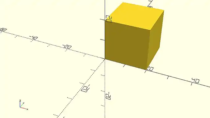
| Try changing the size of the cube to 20 and see what happens. Did you remember to hit preview in order to see your changes take place? |
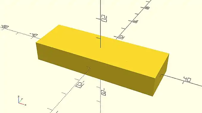
Creating a slightly different cube
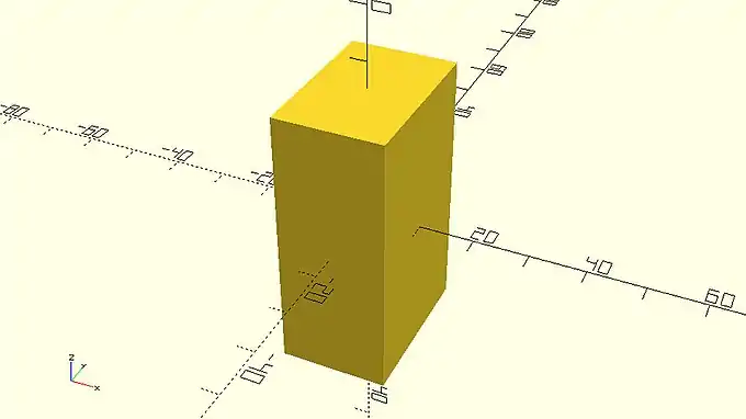
A cube doesn’t have to be perfect. A cube can have different side lengths. Use the following statement to create a cube with side lengths of 20, 30 and 50.
|
a_cube_with_different_side_lengths.scad cube([20,30,50]); |

The first thing that you should notice is that this cube is quite large compared to the previous one. In fact, it is large enough that it doesn’t fit in the viewport. In order to fix this, you can move your mouse over the viewport and scroll out until you can see the whole cube. You can always zoom in and out by moving your mouse over the viewport and using the scroll wheel. Alternatively, you can use the zoom in (fourth) and out (fifth) icons on the action bar below the viewport. You can let OpenSCAD automatically choose a convenient zoom level by using the view all (third) icon in the same action bar.
| Try moving your mouse over the viewport and using the scroll wheel to zoom in and out. Try zooming in and out using the corresponding icons. Let OpenSCAD choose a zoom level for you. |

Apart from zooming in and out you can also move and rotate the view of your model. To do so you need to move your mouse over the viewport and drag while holding right click to move or drag while holding left click to rotate. You can reset the view by using the reset view (sixth) icon on the action bar below the viewport.
| Try dragging your mouse over the viewport while holding right or left click to move or rotate the view of your model. See how long you can mess around before you need to reset the view. |

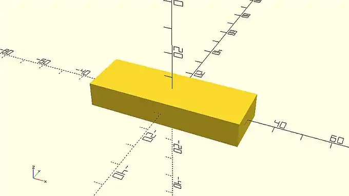
The second thing that you should notice is that in order to create a cube with different side lengths you need to define a pair of brackets with three values inside the parentheses. The pair of brackets is used to denote a vector of values. The values of the vector need to be comma-separated and correspond to the cube side lengths along X, Y and Z axis. When the cube command is used with a vector of three values as its input, OpenSCAD creates a cube with different side lengths that correspond to the values of the vector. Remember that you previously used the cube command to create a perfect cube by defining the value of the parameter size. Most OpenSCAD commands can be used with different parameters, even with more, less or no parameters to achieve different results.
| Try using the cube command with no parameters. What happens? Use the cube command to create a cube with side lengths of 50, 5 and 10. Use the cube command to create a perfect cube with side length of 17.25. |
You should notice that every cube is created on the first octant. You can define an additional parameter named center and set it equal to true in order to make the cube centered on the origin. The complete statement is the following.
|
a_centered_cube_with_different_side_lengths.scad cube([20,30,50],center=true); |
Notice that when more than one parameter is defined inside the parentheses, they need to be separated with a comma.
| Try creating a perfect cube or a cube with different side lengths. Use an appropriate additional input parameter to make this cube centered on the origin. If you like add some whitespace before and after the comma that separates the two parameters. |
Adding more objects and translating objects
The constructive solid modelling approach uses a number of fundamental objects along with a number of ways to transform and combine these objects to create more complex models. The cube that you have been using in the previous examples is one such fundamental object. The fundamental objects are also called primitives and are directly available in OpenSCAD scripting language. A car for example is not an OpenSCAD primitive, as there is no corresponding keyword in the scripting language. This makes absolute sense because OpenSCAD is a set of modelling tools rather than a library of predefined models. Using the available tools, you can combine the available primitives to create your own car. To do this you need to know how to add more than one object to your model.
First create a cube with side lengths of 60, 20 and 10 that is centered on the origin.
cube([60,20,10],center=true); |
In order to add a second cube to your model type an identical statement in the next line of the text editor, but change the side lengths to 30, 20 and 10.
|
a_smaller_cube_covered_by_a_bigger_cube.scad cube([60,20,10],center=true); cube([30,20,10],center=true); |
You should not be able to see any change in your model because the second cube is not larger than the first cube in any direction and is currently completely covered by the first cube. By modifying the second statement in the following way, you can translate the second cube to locate it partially above the top of the first cube.
|
two_cubes.scad cube([60,20,10],center=true);
translate([0,0,5])
cube([30,20,10],center=true);
|
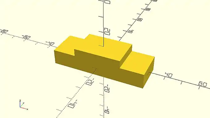
You achieved this by using the translate command which is one of the available transformations. The translate command as well as the rest of the transformations don’t create any object on their own. They are rather applied on existing objects to modify them in a certain way. The translate command can be used to move an object to any point in space. The input parameter for the translate command is a vector of three values. Each value indicates the amount of units that the object will be moved along the X, Y and Z axis. You should notice that there is no semicolon after the translate command. What follows the translate command is the definition of the object that you want to translate. The semicolon is added at the end to indicate the completion of the statement.
| Try changing the input parameter of the translate command so that the cube is translated 5 units along the X axis and 10 units along the Z axis. Try adding some whitespace if you would like to format this statement in a different way. Try adding a semicolon after the translate command. |
|
two_cubes_barely_touching.scad cube([60,20,10],center=true);
translate([0,0,10])
cube([30,20,10],center=true);
|
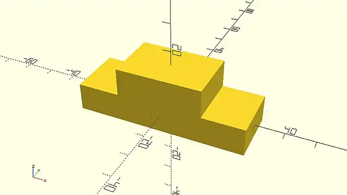
On the example above, the second cube sits exactly on top of the first cube. This is something that should be avoided as it’s not clear to OpenSCAD whether the two cubes form one object together. This issue can be easily solved by always maintaining a small overlap of about 0.001 - 0.002 between the corresponding objects. One way to do so is by decreasing the amount of translation along the Z axis from 10 unit to 9.999 units.
|
two_cubes_with_small_overlap.scad cube([60,20,10],center=true);
translate([0,0,9.999])
cube([30,20,10],center=true);
|

Another way to do so more explicitly is by subtracting 0.001 units from the corresponding value on the script.
|
two_cubes_with_explicit_small_overlap.scad cube([60,20,10],center=true);
translate([0,0,10 - 0.001])
cube([30,20,10],center=true);
|
This is something you are going to encounter throughout the tutorial. When two objects are exactly touching each other a small overlap will be always guaranteed by subtracting or adding a tolerance of 0.001 units.
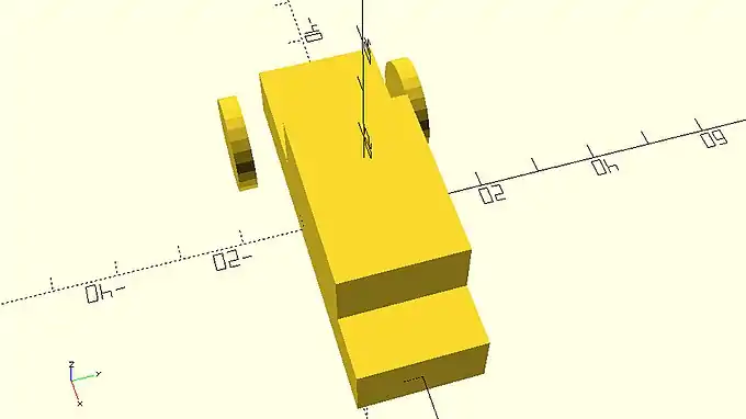
The cylinder primitive and rotating objects
The model that you just created looks like the body of a car that has bad aerodynamics. That’s ok. You will be making the car look a lot more interesting and aerodynamic in the following chapters. For now, you are going to use the cylinder primitive and the rotate transformation to add wheels and axles to your car. You can create a wheel by adding a third statement that consists of the cylinder command. You will need to define two input parameters, h and r. The first one will be the height of the cylinder while the second one will be its radius.
|
a_cylinder_covered_by_cubes.scad cube([60,20,10],center=true);
translate([5,0,10 - 0.001])
cube([30,20,10],center=true);
cylinder(h=3,r=8);
|

You should notice that the cylinder is hidden by the rest of the objects. You can use the translate command to make the cylinder visible by translating it 20 units along the negative direction of the Y axis.
|
two_cubes_and_a_cylinder.scad cube([60,20,10],center=true);
translate([5,0,10 - 0.001])
cube([30,20,10],center=true);
translate([0,-20,0])
cylinder(h=3,r=8);
|

The wheel is now visible, but your car won’t go anywhere if its not properly placed. You can use the rotate command to make the wheel stand straight. To do so you need to rotate it 90 degrees around the X axis.
|
two_cubes_and_a_rotated_cylinder.scad cube([60,20,10],center=true);
translate([5,0,10 - 0.001])
cube([30,20,10],center=true);
rotate([90,0,0])
translate([0,-20,0])
cylinder(h=3,r=8);
|

The first thing you should notice is the absence of semicolon between the rotate and translate command. You should be already getting familiar with this concept. The semicolon is only added at the end of a statement. You can keep adding as many transformation commands as you like in a similar fashion, but you should not include a semicolon between them.
The second thing you should notice is that the rotate command has one input parameter, which is a vector of three values. In complete analogy to the translate command each value indicates how many degrees will an object be rotated around the X, Y and Z axis.
The third thing you should notice is that the wheel is standing straight but as a result of its rotation around the x axis it has moved below the car. This happened because the object was already moved away from the origin before it was rotate. A good practice for placing objects inside your model is first to rotate them and then to translate them to the desired position.
| Try first rotating the wheel and then translating it, by changing the order of the rotate and translate commands. |
|
two_cubes_and_a_rotated_and_translated_cylinder.scad cube([60,20,10],center=true);
translate([5,0,10 - 0.001])
cube([30,20,10],center=true);
translate([0,-20,0])
rotate([90,0,0])
cylinder(h=3,r=8);
|
![]()
It already looks a lot better than the previous position of the wheel.
| Try modifying the input parameter of the translate command to make this wheel the front left wheel of your car. |
|
car_body_and_front_left_wheel.scad cube([60,20,10],center=true);
translate([5,0,10 - 0.001])
cube([30,20,10],center=true);
translate([-20,-15,0])
rotate([90,0,0])
cylinder(h=3,r=8);
|

| Try adding the front right wheel of the car by duplicating the last statement and changing only the sign of one value. |
|
car_body_and_misaligned_front_wheels.scad cube([60,20,10],center=true);
translate([5,0,10 - 0.001])
cube([30,20,10],center=true);
translate([-20,-15,0])
rotate([90,0,0])
cylinder(h=3,r=8);
translate([-20,15,0])
rotate([90,0,0])
cylinder(h=3,r=8);
|
You should notice that the position of the wheels is not symmetric. This happened because the cylinder was not created centered on the origin.
| Try adding an additional input parameter to the cylinder commands to denote to OpenSCAD that both wheels should be centered on the origin when first created. Is the position of your wheels symmetric now? |
|
car_body_and_aligned_front_wheels.scad cube([60,20,10],center=true);
translate([5,0,10 - 0.001])
cube([30,20,10],center=true);
translate([-20,-15,0])
rotate([90,0,0])
cylinder(h=3,r=8,center=true);
translate([-20,15,0])
rotate([90,0,0])
cylinder(h=3,r=8,center=true);
|

Completing your first model
| Try using what you have learned to add the rear missing wheels to the car. Try adding a connecting axle to the front and rear wheels. |
|
completed_car.scad cube([60,20,10],center=true);
translate([5,0,10 - 0.001])
cube([30,20,10],center=true);
translate([-20,-15,0])
rotate([90,0,0])
cylinder(h=3,r=8,center=true);
translate([-20,15,0])
rotate([90,0,0])
cylinder(h=3,r=8,center=true);
translate([20,-15,0])
rotate([90,0,0])
cylinder(h=3,r=8,center=true);
translate([20,15,0])
rotate([90,0,0])
cylinder(h=3,r=8,center=true);
translate([-20,0,0])
rotate([90,0,0])
cylinder(h=30,r=2,center=true);
translate([20,0,0])
rotate([90,0,0])
cylinder(h=30,r=2,center=true);
|
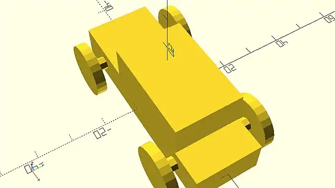
You should notice that on the model above there is an overlap between the axles and the wheels that is equal to half the thickness of the wheels. If the model was created in a way that the wheels and the axles were just touching each other then there would be a need to ensure a small overlap between them like it was done with the two cubes of the car’s body.
One thing that may have bothered you so far is the resolution of the wheels. Until now you have been using OpenSCAD’s default resolution settings. There are special commands in OpenSCAD language which allow you to have full control over the resolution of your models. Increasing the resolution of your model will also increase the required rendering time every time you update your design. For this reason, it advised that you keep the default resolution settings when you are building your model and increase the resolution only after completing your design. Since the car example is completed, you can increase the resolution by adding the following two statements in your script.
$fa = 1; $fs = 0.4; |
Try adding the above two statements at the beginning of the car’s script. Do you notice any changes in the resolution of the wheels?
|
completed_car_higher_resolution.scad $fa = 1;
$fs = 0.4;
cube([60,20,10],center=true);
translate([5,0,10 - 0.001])
    cube([30,20,10],center=true);
translate([-20,-15,0])
    rotate([90,0,0])
    cylinder(h=3,r=8,center=true);
translate([-20,15,0])
    rotate([90,0,0])
    cylinder(h=3,r=8,center=true);
translate([20,-15,0])
rotate([90,0,0])
cylinder(h=3,r=8,center=true);
translate([20,15,0])
rotate([90,0,0])
cylinder(h=3,r=8,center=true);
translate([-20,0,0])
rotate([90,0,0])
cylinder(h=30,r=2,center=true);
translate([20,0,0])
rotate([90,0,0])
cylinder(h=30,r=2,center=true);
|

In reality $fa and $fs are special variables that determine the resolution of the model according to the values that have been assigned to them. Their exact function will be explained later and is something that should not bother you yet. The only thing you need to keep in mind is that you can add these two statements in any script to achieve a resolution that is universally good for 3D printing. These two statements will be used in all examples throughout the tutorial in order to have visually appealing renderings.
Before sharing your script with your friends, it would be nice to include some comments to help them understand your script. You can use a double slash at the start of a line to write anything you like without affecting your model. By using a double slash OpenSCAD knows that what follows is not part of the scripting language and simply ignores it.
| Try adding a comment above each statement to let your friends know what part of your model is created with each statement. |
|
completed_car_commented.scad $fa = 1;
$fs = 0.4;
// Car body base
cube([60,20,10],center=true);
// Car body top
translate([5,0,10 - 0.001])
cube([30,20,10],center=true);
// Front left wheel
translate([-20,-15,0])
rotate([90,0,0])
cylinder(h=3,r=8,center=true);
// Front right wheel
translate([-20,15,0])
rotate([90,0,0])
cylinder(h=3,r=8,center=true);
// Rear left wheel
translate([20,-15,0])
rotate([90,0,0])
cylinder(h=3,r=8,center=true);
// Rear right wheel
translate([20,15,0])
rotate([90,0,0])
cylinder(h=3,r=8,center=true);
// Front axle
translate([-20,0,0])
rotate([90,0,0])
cylinder(h=30,r=2,center=true);
// Rear axle
translate([20,0,0])
rotate([90,0,0])
cylinder(h=30,r=2,center=true);
|
It’s time to save your model. Hit the save (third) icon on the action bar above the editor to save your script as a *.scad file. When you are creating a new model remember to save early and then save often to avoid accidentally losing your work.
If you would like to 3D print your car you can export it as an STL file. You should first hit the render (second) icon on the action bar below the viewport to generate the STL data of your model. You should then hit the export as STL icon on the action bar above the editor to save a STL file of your model.
Creating a second model
| Try using everything you learned to create a new simple model. It can be a house, an airplane or anything you like. Don’t worry about making your model look perfect, just experiment with your new skills! You will keep learning more techniques to create awesome models in the following chapters. |