Foreword
(Note book is under construction)
1. Aim of book
2. Prerequisites
3. Materials
Basics
1. Basic Theory
2.Open/Closed/Short Circuit
3. Circuit Diagrams
Resistors
- Materials - as Chapter 1, but add the multimeter (describe how to measure battery voltage) and high wattage resistors (or use some nichrome wire?; show circuit symbol).
- Voltage drop - connect in series with light bulb and observe drop in brightness, measure with multimeter.
- Ohms law - describe how to measure resistance, then calculate current from voltage drop, do an experiment to check.
- A couple more experiments here...
Capacitors
1. Materials
2. Charging and Discharging
3. more...
Inductors
Semiconductors
Integrated Circuits
Analogue and Digital
Digital Circuits
Microprocessors
Alternating Current
The previous chapters dealt with DC. This chapter gives a brief introduction to AC or Alternating Current. Although most people associate AC with the 120V or 230V outlets, it also involves any other electric signal which change polarity periodically e.g. audio signals.
This chapter will address a small subset of AC signals: single phase AC as it's produced by the electricity company and delivered through the outlets in your home.
A note on safety: This chapter doesn't contain experiments. There are 2 reasons for this. First any interesting experiments would require the use of an oscilloscope. Secondly, experimenting with electricity from an outlet is dangerous in so many ways: Death through electrocution, 3rd degree burns from electricity, house fire after a short circuit,... Schools have special infrastructure to be able to do such experiments in relative safety. Most of them would use a variable AC power supply rather than AC outlets anyway.
What is AC?
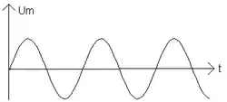
This image shows a typical AC signal. How this signal changes over time is shown. If you've had trigonometry you'll notice the typical shape of the sinus function.
This image shows the amplitude of the AC signal, denoted as Um. This is the highest value the signal reaches.
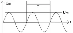
If you look at the 2 lines marked with the T, you'll see they connect 2 identical points on the sine curve. The time it takes to get from the first to the second point is called the period and is indicated with the symbol T. This is a time and therefore expressed in seconds (or more likely milliseconds ms).
Frequency is the inverse of the period: f = 1 / T and is expressed in Hertz (Hz). It's defined as the number of periods per second.
Appendix
See also
- More about specific components
- Circuit Idea reveals the basic ideas behind circuits
- Circuit Theory
- Digital Circuits
- Semiconductors